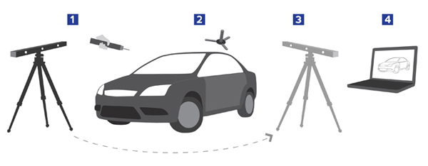
Infrared light from the emitters on a handheld probe (or scanner) is captured by the three cameras on the camera bar. The integrated image processing and control module computes the location and orientation of the tip of the probe.
If a Dynamic Reference Frame (DRF) is used, the control module automatically compensates for relative movement between the part and camera bar.
The DRF can also be used to eliminate the need to “leap frog” the sensor array to a new location, increasing the system’s field of view without compromising accuracy.
The x-y-z and vector data generated by the 3D Creator is continuously passed on to the host computer and further processed by application-specific software (typically CAD/CAM, reverse engineering, or inspection software).
